Mavlink LED Signaling & HoTT
On this page I present an addon that doesn’t require any changes in the AutoQuad code but is built to use the AutoQuad MAVLink output to control LED signals and push telemetry data to a Graupner HoTT transmitter.’ The code is intended to run on an Arduino based processor, it does not really matter what kind but I chose the JDrones IOBoard because it combines an Arduino Pro Mini with 6 high power, high voltage outputs to directly control led strips (0-40V). It can be attached to the AutoQuad FTDI controller, can control up to 6 leds and attach a Graupner HoTT receiver.
Current status: (Dec 2013)
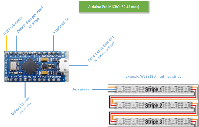
- Support for Arduino Pro MICRO (leonardo bootloader) and Pro MINI based boards
- Can be used as standalone AutoQuad led controller (based on mavlink communication), standalone mavlink to HoTT telemetry bridge or the combination of the two.
- decode all AutoQuad mavlink data
- LED status disarmed, armed, altitude hold, position hold, mission, radio loss, low battery stages and navigation stages (extended mavlink message needed)
- LED sequencer with selectable patterns and colors (with RGB leds).
- Support for different intelligent LED strips, ie WS2811, 2812(b), LP8806 etc.
- HoTT data: Battery, battery remaining gauge, AQ temp, GPS coordinates, heading to AQ, bearing to home, distance to home, vario (altitude), speed, gps status, realtime flighttimer, actual current and current usage (capacity remaining) and more.
- Arduino IDE 1.0 or higher. Select Arduino Pro Mini (5V, 16MHz) ATmega328, or pro MICRO. Make sure to move all libraries from the download to the Arduino “libraries” folder.
- Code in download section
The LED status and display can easily be changed in the code although some (arduino) development skills are needed. You will not find a how to upload or program here because there is a vast amount of info to be find on dedicated sites. The LED sequencer is easily changed in a table similar to the AutoQuad build in led sequencer.

          |
||
How to connect it to the AutoQuad
It is possible to use parallel rx-tx connections to the FTDI port. As long as the signals are on the same voltage level, the mcu can handle this without getting harmed. To ensure no high current can flow, you could consider placing a resistor in both the tx/rx lines. Mav2Hott in its current form will only listen to AutoQuad and not send messages therefor only the AutoQuad TX to Mav2HoTT arduino RX is needed. A 2k2 resistor will keep the lines safe. If there is a difference in voltage between the connected devices (xbee 3.3V + arduino 5V you can place a simple diode in the TX-RX line to the arduino to lower the voltage. All this are only recommendations, it will work without resistors or diodes but is included here to prevent a blown AutoQuad mcu.

Note: Signal wire always points to the white arrow.
Without changes to the Mav2HoTT code, digitalport D5 defaults to HoTT telemetry output. (D9 on arduino pro MICRO!) Just connect 1 wire from d5 to the receiver telemetry port (T). The PPM connection to AQ will provide the GND and close the circuit.
Checksums
If you use AutoQuad r200 or later there are already small changes in the code to output AutoQuad’s status. Just connect the Mav2HoTT arduino, the telemetry port to the receiver and power all on. If you select the receiver and the various telemetry sensors (Mav2HoTT will simulate Vario,GPS,General Air and Electric Air) you should see the data coming on the screens. How to setup the telemetry, the correct port on the receiver etc can obviously read in the Graupner manuals. If the message on the screen is No Mavlink you either have an older AutoQuad version or swapped the RX/TX lines. If no data at all is available and you are sure the transmitter is setup correctly to receive telemetry data then you can troubleshoot the Mav2HoTT by compiling the debug option. With debug you can display all decoded mavlink data using the d5/d6 port and a serial terminal like putty. For the debug you can use the same FTDI usb interface that is used for flashing AutoQuad or connecting AutoQuad to the groundstation. Only the GND and d5 to RX is needed. The (putty) terminal setting needs to be 19200,n,8,1. After powering on a small message will be displayed. If that message is not displayed, check the connections and maybe swap RX-TX on the FTDI.
Find more info about the IOBoard in the jDrones Wiki  Current sensor From v 0.92 a current sensor can be attached to the Mav2HoTT arduino. Any analog port can be used and can be configured in the Mav2HoTT.h file (CONFIG # section). It needs however calibration values like the voltage offset @0A (what does the sensor send when not in use), the sensitivity (how many mV’s per A), the voltage in (for example the 5V from AQ). Those should be available from the vendor and by actual measurements. Once entered and once the AutoQuad is armed the HoTT display should start displaying the current and mAh values. Best to use a known WattMeter to check the values. The best value to change if the HoTT measured values are not correct is the CURR_AMP_PER_VOLT value If the mAh is to high from the actual value, decrease the CURR_AMP_PER_VOLT in 1mV steps, if it is to low increase it in 1 mV steps.
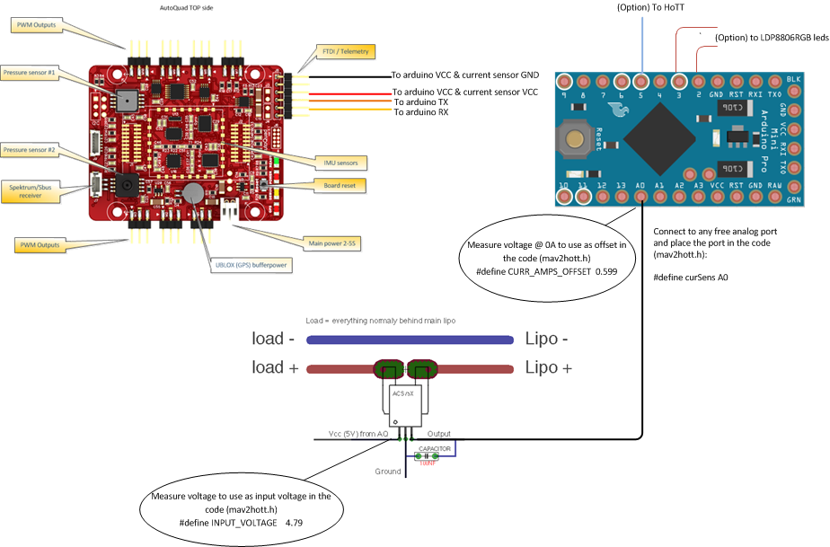
Pro MICRO support: