Assembly of ESC32 V2
Autoquad ESC32v2 comes as a “SMT-preassembled” kit. This means the enduser has add all connections themselves. We did this to keep cost low, and to allow you to configure ESC32 for your exact needs.

Kit contents:
- ESC32 v2, SMT-preassembled and factory tested board.
- 25 cm servo wire with open end.
- Input power wires
- 330uF/35V lowESR capacitor, Panasonic EEUFC1V331B. Its ESR is 68 millohms. Its 50V counterpart is EEUFC1H331L, 60 millohms
Its up to you to configure the wiring so it fits your need and frame. We have shown one way to do it here:
  |
Input Capacitor
The input capacitor is a critical component for ESC operation. The Supplied 330uF/35V capacitor in the kit is safe for “normal” use on up to 4S with continuous currents below 10A. Increase capacitance (add another in parallel or increase size) if:
- Running long wires from battery to ESC (more than 25CM)
- Running high continous currents (remember cooling)
- Using 5S (use 50V capacitor for 5S)
Input Capacitors should be Low ESR types always! (less than 100 milliohms)
Design reference capacitors:
Panasonic EEUFC1V331B, 330uF/35V/68 millohms.
Panasonic EEUFC1H331L, 330uF/50v/60 milliohms (for 5S)
The Input capacitor(s) is soldered directly to the + and – pads on the ESC.
| Observe the input capacitor polarity! The MINUS (-) mark on the capacitor must be connected to the ‘-‘ terminal of the ESC32. Failing this can blow up the capacitor and damage the ESC32! |
Make sure the two capacitor legs are as short as possible and that they cannot be short-circuited to each other – consider using a small piece of shrink-wrap on each leg. Check for solder bridges and shorts across the capacitor legs.
Power Connection
There are multiple ways the main input wires can be connected. We leave it up to you to determine what works best for you. Make sure the there is no shorts across the main power input or the motor phases!
UART Connection
The UART connector matches a standard FDTI style 6-pin connector.
It is used for flashing firmware and connecting to GUI/CLI or running the ESC over the UART interface.

PWM Connection
Solder the PWM servo wire to the PWM pads or add header pins:

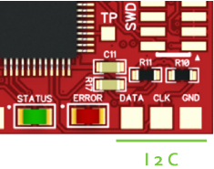
i2c Connection
The ESC32 offers a I2C bus connection for future use. Support for MK I2C control will be released as soon as we had a chance to test it properly – talented people are working on this – a beta release is expected soon.

CAN Connection
ESC32 can be fitted with an optional CAN transceiver (Texas Instruments SNHVD232) to provide CAN-bus control and bidirectional communication at up to 1mbit/s. New ESC32 have the CAN transceiver mounted. CAN is supported in the Firmware.
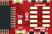
Cortex SWD Connection (J4)
A standard 10-pin SMT cortex SWD connector (Samtec FTSH-105-01-F-DV) can be soldered to the board for realtime debugging of ESC32.

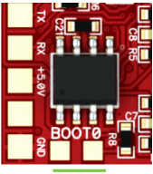
Boot jumper
The boot jumper is used to place the STM32 bootloader in flash mode for uploading new firmware. Short these two pads during powerup to activate the Bootloader and place ESC32 in flash mode (Hint: you can use a pair of tweezers, if you are bit handy – you dont need to keep the pads shortened after the ESC has been powered up. However, if flashing is aborted with “..failed to get init ACK from device”-message keep the boot-pins shortened during the process until it´s completed and message “device rebootet” occurs)
Select Power for Logic Side
The ESC32 has two options for powering the logic side:
• On-board 3.3V LDO powered by main battery (Vb)
• 5V coming from UART or PWM interface (V5)
In most cases (especially when using LiPo batteries larger than 3S) it is recommended to power the ESC MCU with 5V from the PWM or UART interface – either from an external regulator or a UBEC hooked up to the servo rail on your FC or receiver.
Selecting 5V, also means you can power up the logic side separately when
flashing firmware or altering settings over 1-wire or UART interfaces, without
the need to power up the motors.
When using the 5V option to you must always DISCONNECT MAIN INPUT FIRST
before disconnecting the 5V power to PWM or UART interface – disconnecting
5V while the main is still powered can damage the ESC.
To select the power source for MCU, locate the small solder jumper in the
corner on the power side. It’s a simple 3-way solder jumper and works by con-necting the middle pad to either the “Vb” or “V5” pads.
Final Checks before powering up
All ESC´s are tested in factory, before being released. But its a delicate piece of electronics running high currents, so you should Inspect your soldering carefully and make sure there is no shorts or solder splashes before powering up the first time. Measure with multimeter (if you have one) for shorts across the main power, PWM and the 3 motor phases.
First time you power up the ESC, we recommend to have the 5V option selected and hook it up to the AutoQuad widget in Qgroundcontrol or CLI via the UART interface without main power connected.
Alternatively you can hook ESC32 to a simple servo tester or receiver with 5V on the PWM interface. Don’t hook main power yet!
| Note: Your servo tester needs to support >50Hz! Cheap/old units only support up to 40Hz. When using your receiver, trim your throttle channel down on your transmitter to make the ESC32 initialize and arm. |
If the ESC gets 5V and a PWM pulse width of at least 750 microseconds, the green LED will light up showing you that the ESC is receiving a valid signal from your FC, RX or servo tester.
You can now hook a power source to main power and check if the motor runs when you increase throttle. (Its a very good idea to use a small, limited power source like a 9V/500ma DC adapter to perform the first tests. This will secure nothing gets burned in case you have a short in your soldering somewhere. If you hook directly to a high current source (like a lipo battery) and there is a short, you can fry both ESC, battery and motor very quickly.
Inspect your soldering carefully and test the ESC on a limited supply before hooking it to a big battery.
ESC32 is now ready to run as a standard PWM ESC with very high motor refresh rate and a 1000-1950us throttle range with motor start at 1100uS. As such it can now be mounted to your favorite multi and flown right away.
Current and Cooling Considerations
How much current you can actually draw from ESC32, depends on how good they are cooled and where they are mounted.
Our general recommendation is to mount the ESC32 under or near the motors where they get cooled by the prop wash. Continous current drawings of 20A result in a slightly warm ESC. At under 10A per motor, cooling considerations are not needed. The gate-driven design means that the ESC´s wont warm up considerably when run at low currents.
The upper limit is probably upwards of 50A, but that will require extremely good cooling. The factory default for the current limiter in the firmware is 20A continuously. Going beyond that limit will require attention to proper cooling and temperature of the ESC.
Bear in mind that most “normal” setups under 3kg will stay well under 20A continuously per motor in normal flight conditions and hover (or something is very wrong with your choice of motors and props).
Always test your individual setup and if you see signs of the ESC heating up it means you should add cooling. The better you cool your ESC´s, the more efficient they will also be so! In theory, they should continue to operate up to around 70-80 celsius, but they will age faster when run at high temps!
The best strategy keep ESC´s cool in a multirotor, is to place them in the wash from the rotors (Ideally right under the motors). In frames where that is not possible because of wiring considerations or if running high currents, heatsinks should be applied to the FETS on both sides. In general its not good practice to place ESC´s in tight places without any airflow, especially if running high currents!
LED Signals
| red flashing | no valid PWM signal (<750us or > 2100us) prop strike over current |
| green | ready / armed |
| off | running mode |
| Please be very careful running a calibration! Your motors will perform certain patterns up to full power. Make sure to run these tests only in a secured environment! Only use it in closed rooms or boxes where propellors can fly off without hurting anyone or damaging anything! |
Note: You can download these instructions as PDF file from our Download section.


